




A thermistor may be a small component, but the wiring around it can affect the temperature signal significantly. Lead resistance, poor crimps, moisture, self-heating, cable routing, and an incorrect controller curve can all produce inaccurate or unstable readings.
The good news is that most two-lead NTC thermistors are simple to connect. The key is understanding what the sensor is—and what has been added around the sensing element.
This guide explains thermistor polarity, NTC wiring, lead-resistance effects, connectors, cable extensions, multi-wire probes, and practical troubleshooting methods for equipment designers and maintenance teams.
Does a Thermistor Have Polarity?
A conventional two-lead NTC thermistor does not have polarity. It behaves as a temperature-dependent resistor, so either lead can be connected to either terminal of the controller input.
A two-lead ceramic PTC thermistor is also generally non-polarized. Reversing the leads does not change the resistance measurement.
There are important exceptions:
Silicon PTC sensors, such as some KTY-series devices, may require the correct current direction for the specified resistance-temperature curve.
Three- or four-wire probes may contain multiple sensing elements, bridge resistors, a shield, or a ground connection. Their conductors are not automatically interchangeable.
Customized sensor assemblies may include electronics or protection components that assign a function to each wire.
If a sensor has more than two wires, follow its wiring drawing instead of assuming that it is a simple thermistor.
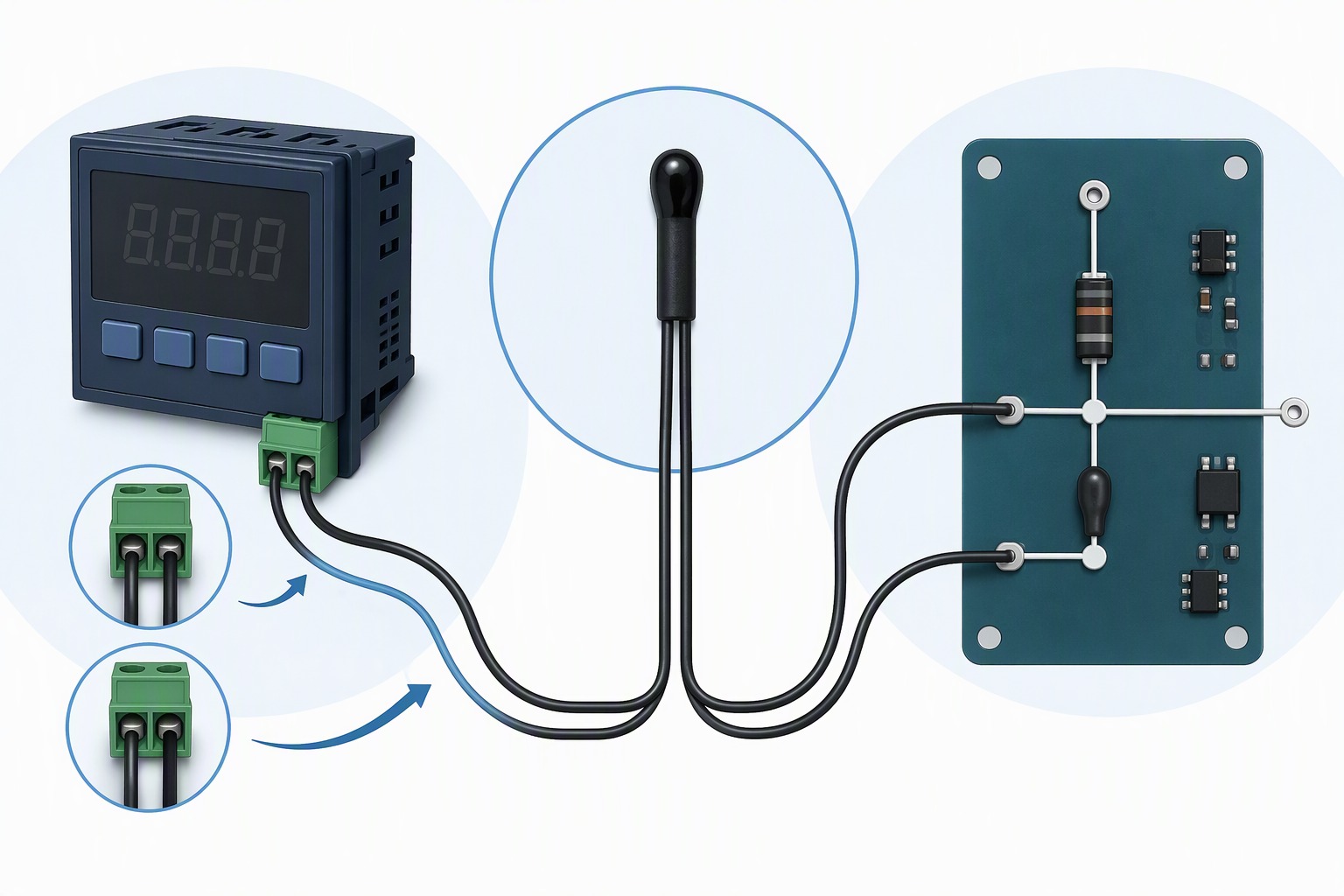
Illustrative technical diagram: a conventional two-lead NTC thermistor connected to a controller input and measurement circuit.
How to Wire a Two-Lead NTC Thermistor
A controller with a dedicated thermistor input normally requires two connections. Connect the two NTC leads to the two sensor terminals in either order, then configure the controller for the correct sensor curve.
The curve setting must match the thermistor’s electrical characteristics, including:
Nominal resistance at 25°C, often called R25
B-value or beta value
Resistance tolerance
Applicable temperature range
Controller-specific curve type, such as Type 2, Type 3, or 3950
A sensor with the wrong R25 or B-value may produce a large temperature error even when the wiring is physically correct.
NTC Thermistor Voltage-Divider Circuit
When an NTC is connected to a microcontroller or a general analog input, it is commonly used with a fixed resistor as a voltage divider:
Connect the fixed resistor between the reference voltage and the analog-input node.
Connect one NTC lead to the same analog-input node.
Connect the other NTC lead to ground.
Select a fixed-resistor value appropriate for the operating temperature range.
Convert the measured voltage into resistance and then temperature in firmware.
For a 10 kΩ NTC, a 10 kΩ fixed resistor provides a useful midpoint near 25°C. If the sensor operates mainly at a higher temperature, a lower fixed-resistor value may improve sensitivity in that working region.
The resistance of an NTC can be approximated with the beta equation:
T=T01+B1ln(R0R)1
where T and T0 are absolute temperatures in kelvin, R is the measured resistance, R0 is the reference resistance, and B is the beta value.
For higher accuracy, use the manufacturer’s resistance-temperature table or Steinhart-Hart coefficients instead of relying only on a simplified beta equation.
How Lead Resistance Affects NTC Measurements
Any cable, connector, crimp, solder joint, or terminal placed in series with the thermistor adds resistance to the measurement loop.
For an NTC thermistor, extra series resistance normally makes the controller interpret the sensor as colder than it really is. The effect becomes larger when:
The sensor temperature is high and its resistance has fallen
The cable is long or uses a small conductor
The thermistor has a relatively low nominal resistance
The connector or crimp is damaged or contaminated
A 10 kΩ NTC is relatively tolerant of ordinary cable resistance. A low-resistance thermistor, such as a 2 kΩ or 2.252 kΩ device, is more sensitive to the same cable length.
Practical Cable-Resistance Calculation
For a two-conductor cable, the loop resistance is approximately:
Rloop=2×L×Rcable
where L is the one-way cable length and Rcable is the resistance per unit length of one conductor.
When selecting a cable, consider the complete loop rather than only the distance from the sensor to the controller. Also allow margin for connector contacts, crimps, splices, temperature effects, and production variation.
For precision applications, evaluate the resistance error at the highest expected sensor temperature, because an NTC’s resistance is lower in that region.
Connectors, Crimps, and Solder Joints
A good connector should add very little resistance. In practice, however, the connection may become the largest source of error when it is:
Poorly crimped
Over-crimped
Contaminated by oxidation or moisture
Mechanically loose
Exposed to vibration
Used outside its temperature rating
Subjected to repeated bending or cable pull
An intermittent connection often appears as a temperature value that jumps when the cable or connector is moved. A completely open circuit may be displayed as an extremely high resistance, a low-temperature reading, or an open-sensor fault, depending on the controller.
A short circuit usually appears as very low resistance, a high-temperature reading, or a short-sensor fault.
Connector Selection Checklist
Before selecting a connector for a thermistor assembly, check:
Contact resistance
Current and voltage rating
Operating-temperature range
Moisture and sealing requirements
Vibration resistance
Terminal and crimp compatibility
Required mating cycles
Available locking and strain-relief features
Material compatibility with the cable jacket and sensor housing
The connector rating must match the installation location. A connector suitable for an indoor control cabinet may not be suitable beside a high-temperature probe or inside a humid refrigeration system.
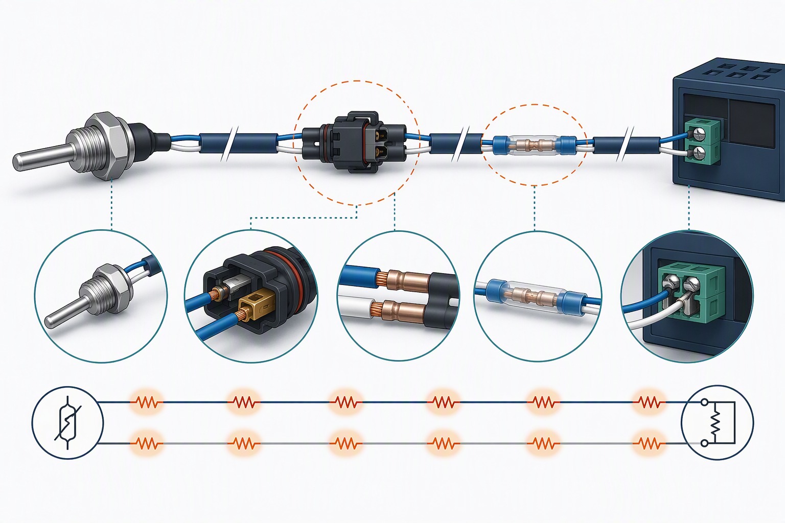
Illustrative technical diagram: cable, connector, crimp, and splice points can all contribute to the sensor loop.
Can Thermistor Wires Be Extended?
Yes. Most NTC and PTC thermistor cables can be extended with suitable stranded copper wire. Unlike a thermocouple, a conventional thermistor does not require a special thermocouple extension alloy.
The extension cable should be selected according to four factors:
1. Conductor resistance
Use a suitable wire gauge for the cable length, sensor resistance, and required accuracy. Long runs to hot sensors require more attention than short room-temperature connections.
2. Jacket temperature rating
The cable near the sensor may be exposed to the same environment as the probe. PVC is common for moderate temperatures, while silicone, PTFE, fiberglass, or other high-temperature constructions may be required in hotter areas.
3. Environmental protection
Moisture entering the cable or splice can create leakage between conductors. Leakage may make the thermistor appear to have a lower resistance and can shift the reading in the warmer direction, especially when the sensor resistance is high at low temperatures.
Use heat-shrink tubing, overmolding, sealed connectors, or a suitable waterproof splice where required.
4. Mechanical strain relief
The most fragile point is often the transition between the sensing element and the cable. Secure the probe so bending occurs in the jacketed cable rather than directly at the thermistor body or solder joint.
Long Cable Runs: Resistance Versus Electrical Noise
A long cable does not always create a large resistance error on a high-resistance NTC. It may, however, increase susceptibility to electrical noise.
For long runs:
Use twisted-pair cable where appropriate.
Keep sensor wiring away from motor, relay, inverter, and mains wiring.
Avoid running low-level sensor cables in the same conduit as power cables.
Use shielded cable in electrically noisy environments.
Ground the shield according to the controller manufacturer’s instructions, often at one end only.
Add filtering or signal averaging when the application allows it.
Thicker wire reduces resistance. It does not necessarily solve electromagnetic interference. Cable routing, shielding, grounding, and input filtering may be more important than conductor size in a noisy installation.
Understanding Two-, Three-, and Four-Wire Thermistor Probes
The thermistor element itself has two electrical terminals. Additional wires indicate that the assembly contains more than a basic two-terminal element.
Two-wire probe
A conventional two-wire probe normally contains one thermistor and has no polarity. Both wires carry the measurement current.
Three-wire probe
A three-wire probe may contain:
Two thermistors sharing a common lead
A thermistor plus a fixed bridge or completion resistor
A signal pair plus shield or ground
A PT100 or PT1000 RTD rather than a thermistor
Measure each pair of wires and compare the results with the product drawing. Do not connect a three-wire probe based only on wire color.
Four-wire probe
Four-wire assemblies may contain two sensing elements, separate signal and excitation conductors, a shield, or integrated electronics. The wiring function must be confirmed from the supplier’s drawing or specification.
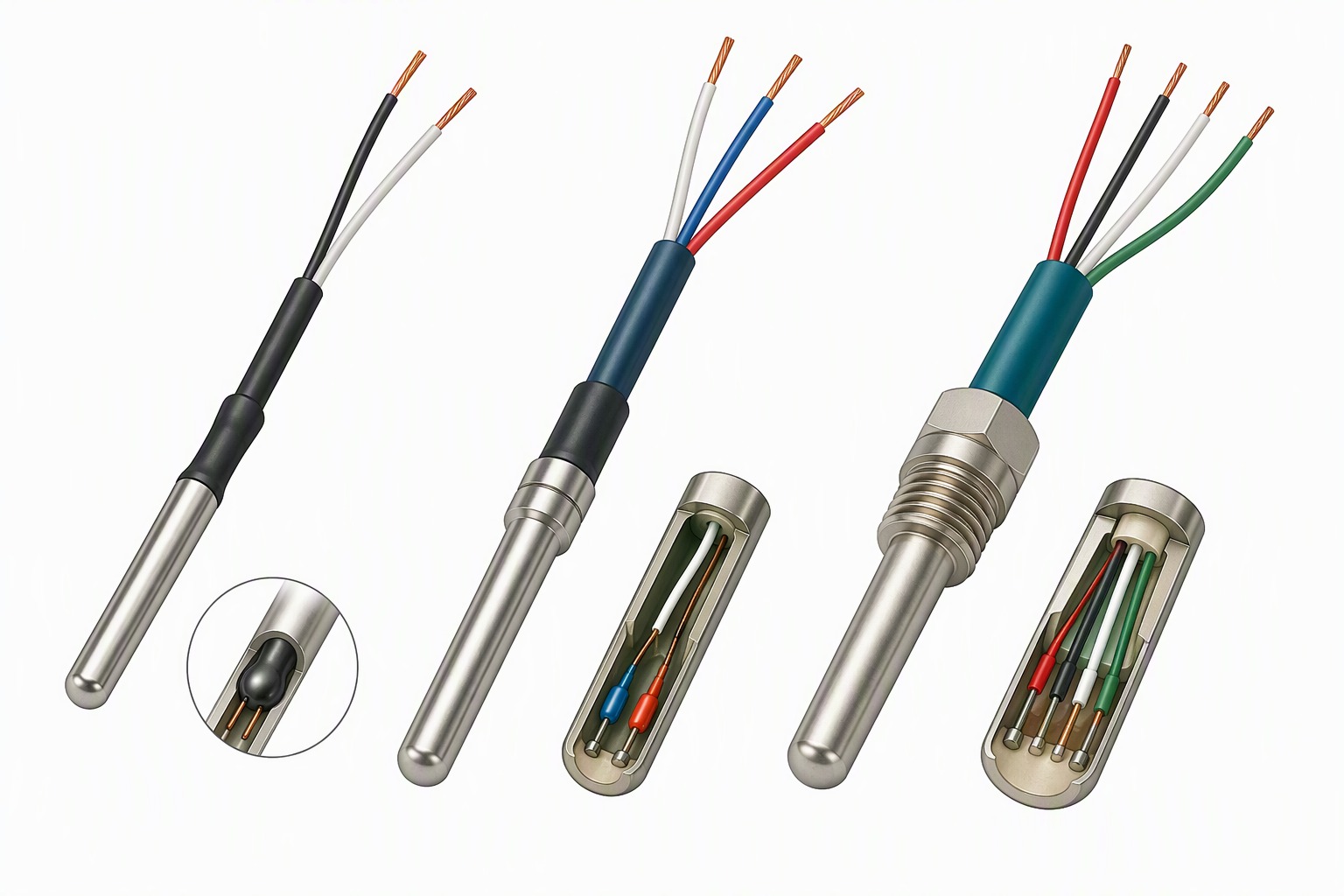
Illustrative technical diagram: wire count alone does not identify the electrical function of a customized sensor assembly.
PTC Motor-Protection Thermistor Wiring
PTC thermistors used for motor-winding protection are not wired like a single NTC measurement probe. Multiple PTC elements are commonly connected in series, with one sensor placed in each motor winding or monitored zone.
The PTC circuit connects to a dedicated thermistor relay or motor-protection device. Use the relay manufacturer’s limits for:
Maximum line resistance
Maximum cable length
Sensor count
Short-circuit detection
Open-circuit detection
Test voltage
Separation from motor power conductors
Motor-protection PTC wiring should use a separate control circuit rather than cores from the motor power cable when the equipment documentation requires that arrangement.
Thermistor Wiring Troubleshooting Checklist
If a thermistor reading is inaccurate or unstable, check the following in order:
Confirm the sensor type. Is it an NTC, ceramic PTC, silicon PTC, PT100, PT1000, or a customized assembly?
Verify the controller curve. Confirm R25, B-value, curve type, and temperature range.
Measure the sensor at a known temperature. Compare the resistance with the supplier’s resistance-temperature table.
Check for an open circuit. Inspect the element, cable, crimp, connector, and solder joint.
Check for a short circuit. Look for damaged insulation, crushed cable, moisture, or conductive contamination.
Measure cable loop resistance. Disconnect the probe and measure the extension cable separately.
Flex the cable and connector. A changing reading suggests an intermittent connection.
Check self-heating. Excessive measuring current can make the sensor read warmer.
Inspect cable routing. Separate sensor wiring from high-voltage and motor cables.
Check insulation and sealing. Moisture leakage can create errors that are difficult to reproduce in dry conditions.
Focusens Thermistor Probes and Cable Assemblies
Focusens supplies NTC thermistor probes, epoxy and glass-encapsulated sensors, ring-lug temperature sensors, and customized cable assemblies. You can review the NTC thermistor sensor and probe range and cable assembly and wire harness range.
For a customized thermistor assembly, provide the following information:
R25 and B-value
Temperature range
Accuracy or tolerance
Cable length and gauge
Cable jacket material
Connector type
Waterproofing or sealing requirement
Installation method
Controller or circuit interface
Expected operating environment
Focusens can evaluate standard and customized configurations, including epoxy NTC sensors with extension cables and ring-lug surface temperature sensors.
Frequently Asked Questions
Does it matter which way an NTC thermistor is wired?
No. A conventional two-lead NTC thermistor has no polarity and can be connected in either direction. Check the drawing for silicon PTC sensors and probes with more than two wires.
Can I extend an NTC thermistor cable?
Yes. Use suitable copper cable, a reliable sealed splice or connector, appropriate insulation, and strain relief. Check the added loop resistance if the cable is long, the sensor resistance is low, or the application requires high accuracy.
What causes an NTC thermistor to read colder than the actual temperature?
Common causes include series resistance from cable or contacts, an incorrect controller curve, a wrong B-value, or a sensor installed where it does not make good thermal contact.
What causes an NTC thermistor to read warmer?
Self-heating, moisture leakage, an incorrect curve, or poor thermal contact with a warmer nearby component can cause a higher indicated temperature. Electrical noise can also create unstable readings.
How do I identify a three-wire thermistor?
Measure resistance across all wire pairs and compare the results with the product drawing. A three-wire assembly may contain two thermistors, a bridge resistor, a shield, or an RTD. Wire color alone is not enough for identification.
Are thermistors connected in series?
A measuring NTC is commonly placed in series with a fixed resistor to create a voltage divider. Motor-protection PTC elements are commonly connected in series so that an over-temperature condition raises the circuit resistance and trips the protection relay.
Conclusion
Thermistor wiring is straightforward when the sensing element and the complete assembly are understood.
A standard two-lead NTC has no polarity. The main wiring risks are incorrect controller settings, added series resistance, poor contacts, moisture leakage, self-heating, cable damage, and electrical interference.
For reliable results, match the thermistor curve to the controller, evaluate cable resistance at the highest operating temperature, select connectors for the actual environment, protect splices from moisture, and verify every conductor on a multi-wire probe before connection.
For a customized NTC thermistor sensor solution, provide the electrical, mechanical, environmental, and connector requirements so the sensor and cable assembly can be designed as one system.

Expert for Thermistors Temperature Sensors Humidity Sensors Level Sensors ; Reliable but flexible custom products development
100+ Sensing Solutions Developed Annually for Different Applications
80+ Countries Customers Serviced


